Fuel Pump
2002 C240: Fuel Level Sensor/Pump Replacement
When viewing, using, and/or any other method applied to this publication you agree to the following statements. You, your next of kin, heirs or assigns release www.installuniversity.com, all other persons associated in the making, production, and participation of this publication. Rephrased in plain English: When you view this web page you, your next of kin, heirs or assigns agree not to sue any associated persons with the publication for any accident or damage in ANY form (mental or physical to your car and/or yourself) because of this publication, or your failure to heed proper safety, maintenance and/or modification procedures. You also agree that your next of kin, heirs or assigns cannot sue all persons associated in the making, production, participation, and publishing of this publication.
Perform all these installs at your own risk. Know how to use all of your shop equipment, and take necessary safety precautions when performing ANY modifications and or maintenance items to your vehicle. Seek the advice of a paid professional and do not substitute this publication for the advice of a paid professional. This product is how we accomplished our installs and is not meant to be carved in stone. InstallUniversity.com is not responsible for a mistake, misprint, or any other error found in this guide. This guide is intended as a supplement and not to be your only source of information.
Symptom(s): After completely filling the gas tank, the gas gauge on the dash reads 3/4 of a tank of gas. After 200 miles of driving, the reserve light comes on signaling that the gas tank should be filled immediately. After filling up, only 10 to 11 gallons of gas will be used to fill the tank. This means that 5 to 6 gallons of gas were in the tank.
Date Repaired: 10.162004 Mileage: 86,000
Quote to fix from local MB dealer: $740
Part information, cost, were purchased:
1. Right (passenger) side fuel sending unit - 2034703594 - $170 - MB of Knoxville
2. Left (driver) side fuel sending unit (contains new fuel pump) - 2034700241 - $210 - MB of Knoxville
3. Tool to remove lock ring - XXX - $149.70 - MB of Knoxville
4. Rubber Seal Rings - A2034710179 -$7.80 - MB of Knoxville
5. Two standard hose clamps - $0.40 Each - ACE Hardware
Time it took to install: 90 minutes
Complexity of Install: Medium
Tools needed for this install:
1. Ratchet
2. short socket extension (3" will do)
3. 1/2" socket
4. 10 mm socket
5. Large fan
Install Contributors
1. Steven Lewis (a.k.a. saturnstyl @ MBWorld.org)
2. Sleepwalker
3. Phil Watson
4. Jasmel Sidhu
5. mbtech208
Introduction
Do this at your own risk. This is the procedure I used to replace the fuel level sensors in my car. This is meant for entertainment purposes only and to remind me what parts and procedure used when I look back upon this document.
Lots of gasoline fumes will fill the car. Perform this modification in a well ventilated area and be careful not to inhale the fumes.
More than likely your car will have the fuel level sensors go out. This seems to be a common problem with all Mercedes Benz vehicles. You will have to pull the part numbers off of the top of the fuel level sensors before you order the parts. The part numbers change with the wind at Mercedes involving these units so go in prepared because you will received updated part numbers.
The part numbers pulled off the tops of the compartments are as follows:
1. Passenger Side (Right Side): 2034701394
2. Driver Side (Left Side): 2034700241
The part numbers for the parts I actually received from the dealership:
1. Passenger Side (Right Side): 2034703594
2. Driver Side (Left Side): 2034703041
Warning!
I started the installs and got the hose clamps removed once staurnstyl informed me how. Thanks. I unplugged both connections, then removed the big hose (closest to the front of the car). Up to this point, everything is going great. Then I proceeded to remove the smaller hose, closer to the rear of the car. Big MISTAKE! Gas starts flying EVERYWHERE!!! DOH! Words cannot express the feelings I had at the moment. I finally wrestled the hose back on the nipple but it had already depressurized.
Installation Procedure
1. Be sure there is less than 1/8th of a tank of gas in the fuel tank before starting this installation. Failure to do so, could result in flooding the cabin with gasoline.
2. Remove the rear seat cushion. This is accomplished by removing four black nut covers found along the leading edge of the seat cushion as shown in Figure 1. I found the only way I could remove them was to just pry them off with my fingers. Please note a tab found on the inside was broken on all of them after doing this. However, I cannot tell a difference once they are reapplied. I do not know if the tab is functional or not, but the covers seemed unaffected with the broken tab. If someone knows the correct way to remove these covers, and I am sure there is a special tool, please let me know so I can at least present this to those who don't mind spending the money on the tool.
3. Remove each nut found under the black covers. There should be four nuts to remove using a 1/2" drive socket and short extension. You can find the four nuts in Figure 2.
4. Lift up on the front of the seat cushion and pull it towards the front of the car. You will find that it comes out fairly easy. Be careful with the seat, I would hate to think how much the leather cover on it cost.
FYI: You can turn the seat upside down and take a look at the back side of it. Notice that two bungee cords hold the leather cover on.
5. Locate and remove the insulation, see Figure 3, on the floor underneath where the seat cushion was. Gently pull the insulation out making sure you don't tear it. The insulation has guide holes in it where it is wrapped around metal pins that protrude out from the floor of the car.
6. Locate two round plastic panels, shown in Figure 4, on the passenger and driver's side of the car. Each cover has eight screws that will need to be removed using a 10 mm socket shown in Figure 5.
7. At this point, the fuel lines need to be depressurized. This step will help decrease the amount of fuel that spews out of line when you disconnect it on the passenger side fuel level sensor. It will NOT eliminate all the fuel overspray. Caution still needs to be exercised to avoid being sprayed by gasoline while disconnecting the line in later steps.
Locate the top of the driver side fuel level sensor in Figure 6. Unplug the second electrical module shown in Figure 7. Then start the car and let the car run until it shuts off. Then start the car one more time to get all the gas you can out of the fuel lines. Remove the key from the ignition and set it far away from the car where no one will be tempted to mess with it until the installation is over.
8. In Figure 8, the passenger side fuel level sensor compartment is exposed. Notice the black ring with the ribs. This lock ring needs to be removed. I tried to remove the ring by hand, and I had no luck budging the ring. Mercedes Benz requires a special tool to remove the lock rings. The tool has to be ordered through Mercedes Benz (local dealership parts department) and runs around $147.60.
Place the special tool on the lock ring, refer to Figure 9, place a 12mm socket on the top of the tool, and turn it counterclockwise to loosen the ring.
9. Once the lock ring is removed, take note of where the location arrow is pointed. You will need this information upon reinstallation. Grab hold of the fuel level sensor top (the white piece), and pull it out (refer to Figure 10). It should come out relatively easy but will want to stick to the gasket (the green in Figure 10) somewhat. Remove the gasket too and inspect for any damage. If there is not any damage, it will be ok to reuse the gasket. We developed a tear in this gasket when removing. Lay the lid and gasket aside outside the car, being careful not to drip any gasoline inside the car on the interior. Gas fumes will start coming out of the fuel tank at this time so be very careful and take appropriate precautions! Do not drop any particles or contaminants in the tank. Small particles may be picked up by the pump and cause a failure.
10. Please read this step completely before executing. The notes in read at the end are extremely important to read. The passenger side fuel level sensor, which also contains the fuel pump, is now exposed from the top. You will need to disconnect one electrical module and two lines before removing the fuel level sensor. Figure 11 shows the electrical module and two lines that need to be disconnected. The electrical module just needs to be removed by pushing on the clasp. The top line should be squeezed and pulled in the area where there is no supports. The bottom line is removed by pulling down on the tab underneath the line, and then pulling the line. The bottom line will be pressurized and will spew gas gasoline while be disconnected. I suggest you disconnect the line with great care and keep the unit as far in the compartment away from the access hole as much as possible. Once the three connections have been disconnected, you can remove the fuel level sensor from the compartment.
Please note that the fuel level sensor/fuel pump housing, will be FULL OF GASOLINE. Empty what you can inside the tank by tipping the unit over as best you can. Please be careful not to tip the unit while removing it from the car so you don't spill any gasoline inside the car. Please dispose of the unit in a safe and appropriate manner in accordance with your local regulations and laws.
11. Locate the top of the driver side fuel level sensor in Figure 12. Unplug the second electrical module, this module sends the actual fuel level in the tank to the cluster, shown in Figure 13.
12. Remove the two hose clamps on each of the lines on top of the driver side fuel sensor shown in Figure 14. You will need to use needle nose pliers or a small flat head screwdriver to remove the hose clamps. Be careful not to puncture the hoses. Toss the clamps in the garbage, they are useless once you remove them. You will need two replacement clamps, regular hose clamps available at any home improvement or auto parts store as shown in Figure 15, which should have been purchased before you reached this step.
13. Remove hose #1, shown in Figure 16, that is closest to the front of the car. Place a rag over the hose while you remove it. It may take a little force to remove the hose but once it starts to move, it should slide off.
14. Remove hose #2, shown in Figure 17, that is closest to the rear of the car. This hose will definitely have fuel in it and great care should be taken to keep overspray from getting all over the inside of the car. Place a rag over the hose while removing it to help protect the interior of the car from gasoline spray.
15. In Figure 18, the driver side fuel level sensor compartment is exposed. Remove the black lock ring using the special Mercedes Benz tool. Be careful not to tear or damage any of the hoses or electrical modules while removing the lock ring. It is easy to do so take special care.
Place the special tool on the lock ring, refer to Figure 18, place a 12mm socket on the top of the tool, and turn it counterclockwise to loosen the ring.
16. Once the lock ring is removed, take note of where the location arrow is pointed. You will need this information upon reinstallation. Grab hold of the fuel level sensor top (the white piece), and pull it out. It should come out relatively easy but will want to stick to the gasket somewhat. The sensor will come out in one piece, there is no lid like the passenger side, and will have the wires and lines connected to it that you disconnected on the passenger side fuel level sensor. Lay the sensor aside outside the car, being careful not to drip any gasoline inside the car on the interior. Gas fumes will start coming out of the fuel tank at this time so be very careful! Do not drop any particles or contaminants in the tank. Small particles may be picked up by the pump and cause a failure. Please dispose of the unit in a safe and appropriate manner in accordance with your local regulations and laws.
17. Remove the gasket, if it didn't come out with the fuel level sensor, and inspect it for damage. It is ok to reuse this gasket if no damage is found but we decided to toss it in the garbage and to just replace it with a new one. No reason to start saving $5 at this point. Lay the gasket aside outside the car or dispose of it properly.
18. It is time to replace the driver side fuel level sensor unit. Place the gasket in the neck of the access port in the gas tank as shown in Figure 19. This will be easier than installing the gasket on the unit before installation. Be sure the gasket is seated properly.
19. Install the new driver side fuel level sensor into the fuel tank as shown in Figure 20. The wires and lines will need to be run across to the passenger side of the car. The access tunnel is in the front of the fuel tank where the wires and lines will need to be run. Take great care not to bend the float arm assembly. The float arm assembly is delicate and can be broke or bent easily.
Once the fuel level sensor is in be sure to line the arrow up in the correct position (see Figure 21). Take great care that the sensor is seated properly on the gasket and that there are no folds or missing sections in the gasket. If there is any imperfection in the gasket seat a leak will form! Please check the gasket several times before deciding to proceed to the next step.
20. Once you are sure that the fuel level sensor unit is seated properly on the gasket, and that the arrow is turned in the correct direction, reinstall the lock ring using the special tool/ratchet combination (see Figure 22). I do not have a torque specification on how tight to install the ring, but I can tell you I put it on "tight".
21. Reattach both black hoses to the correct hose bibs shown in Figure 23. Be sure to slide the new hose clamps over the house before installation to speed things up. I tightened the hose clamps to "snug". Do not install the electrical modules at this time. Unfortunately, I didn't snap a picture of the new hose clamps on the newly installed driver side fuel level sensor. Just imagine I have the new clamps installed. DO NOT connect the electrical modules at this point! Wait until both access ports have been securely installed.
22. Install the new fuel level sensor unit/fuel pump housing in the passenger side compartment. Take great care not to bend the float arm assembly. The float arm assembly is delicate and can be broke or bent easily. It will take a little maneuvering, but the fuel level sensor will go through the access port, I promise! Please install the electrical module on top of the unit and then the two lines. Once all three connections have been made, place the unit on the bottom of the tank in the same manner as in Figure 24.
23. Install a new gasket, or reuse the old one if it is in suitable condition, in the passenger side fuel level sensor top and turn it to the correct direction (see Figure 25). The arrow should be pointing directly toward the driver side fuel level sensor access port.
You will need to align the top and bottom units so that both units mesh into one. This may be difficult if you have a lot of gas in your tank. It is also possible that the fuel level sending unit may flip over in the tank during this install. The fuel level sending unit should be placed flat on the bottom of the gas tank.
Just take your time and if you have any question whether the unit is seated and aligned properly, take the top off and start over. We hit it on the first try so I don't expect you will have much problem. The more gas in the tank, the more problematic it will be to perform this step.
24. Once the top, bottom unit, and the gasket installed correctly, reinstall the lock ring, shown in Figure 26, to "tight" using the special Mercedes Benz tool.
25. Now that you have everything physically installed and sealed up, go ahead and reconnect the electrical modules on the driver side fuel level sensor top shown in Figure 27.
26. Place the key in the ignition and move it to position three. Position three is the last stop before actually starting the car. You will hear the fuel pump kick on and start pumping. Check the hoses for leaks at this point.
Start the car. My car started right up with little hesitation. Check the two black hoses on top of the fuel level sensor for leaks as shown in Figure 27. Ignore the fact that new hose clamps are not installed. I didn't snap a photo of them so I have to show the old clamps.
27. Once the hoses have been checked and no leaks found while the car is running, you may want to take a drive to the nearest gas station and fuel up to check the gaskets under the lock rings for leaks (see Figure 26 and 27). Please understand you are suppose to check for leaks if you haven't noticed by now.
I drove 3 miles to the gas station and put a full tank of gas in. The gauge went to full and no leaks around the lock rings. However, it is a loud ride to the gas station with the rear seat out and the access ports off.
28. Back in the garage, reinstall the eight, 8 mm screws on the driver and passenger side access ports shown in Figure 28. Tighten them to "snug".
29. Reinstall the insulation shown in Figure 29 taking care to get the seat belts around the insulation. Before the insulation is put down, a lot of Febreeze may be in order. I sprayed Febreeze everywhere under the insulation just in case some gas is hanging around.
30. Reinstall the seat and be sure to pull all the seat belt locks through the seat. Reinstall the four 10 mm nuts to snug as shown in Figure 30.
31. Reinstall the black nut covers, shown in Figure 31, by snapping them back on. I broke all of the tabs on the backside of the covers when I took them off without knowing the trick to taking them off.
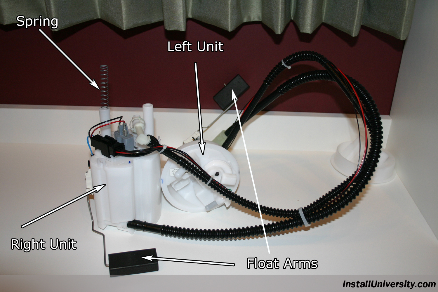
32. Figure 32 shows a general overview of the new units connected together before they are installed.
33. That's it! Your done. You saved yourself money and picked up a tool along the way.
When viewing, using, and/or any other method applied to this publication you agree to the following statements. You, your next of kin, heirs or assigns release www.installuniversity.com, all other persons associated in the making, production, and participation of this publication. Rephrased in plain English: When you view this web page you, your next of kin, heirs or assigns agree not to sue any associated persons with the publication for any accident or damage in ANY form (mental or physical to your car and/or yourself) because of this publication, or your failure to heed proper safety, maintenance and/or modification procedures. You also agree that your next of kin, heirs or assigns cannot sue all persons associated in the making, production, participation, and publishing of this publication.
Perform all these installs at your own risk. Know how to use all of your shop equipment, and take necessary safety precautions when performing ANY modifications and or maintenance items to your vehicle. Seek the advice of a paid professional and do not substitute this publication for the advice of a paid professional. This product is how we accomplished our installs and is not meant to be carved in stone. InstallUniversity.com is not responsible for a mistake, misprint, or any other error found in this guide. This guide is intended as a supplement and not to be your only source of information.
Symptom(s): After completely filling the gas tank, the gas gauge on the dash reads 3/4 of a tank of gas. After 200 miles of driving, the reserve light comes on signaling that the gas tank should be filled immediately. After filling up, only 10 to 11 gallons of gas will be used to fill the tank. This means that 5 to 6 gallons of gas were in the tank.
Date Repaired: 10.162004 Mileage: 86,000
Quote to fix from local MB dealer: $740
Part information, cost, were purchased:
1. Right (passenger) side fuel sending unit - 2034703594 - $170 - MB of Knoxville
2. Left (driver) side fuel sending unit (contains new fuel pump) - 2034700241 - $210 - MB of Knoxville
3. Tool to remove lock ring - XXX - $149.70 - MB of Knoxville
4. Rubber Seal Rings - A2034710179 -$7.80 - MB of Knoxville
5. Two standard hose clamps - $0.40 Each - ACE Hardware
Time it took to install: 90 minutes
Complexity of Install: Medium
Tools needed for this install:
1. Ratchet
2. short socket extension (3" will do)
3. 1/2" socket
4. 10 mm socket
5. Large fan
Install Contributors
1. Steven Lewis (a.k.a. saturnstyl @ MBWorld.org)
2. Sleepwalker
3. Phil Watson
4. Jasmel Sidhu
5. mbtech208
Introduction
Do this at your own risk. This is the procedure I used to replace the fuel level sensors in my car. This is meant for entertainment purposes only and to remind me what parts and procedure used when I look back upon this document.
Lots of gasoline fumes will fill the car. Perform this modification in a well ventilated area and be careful not to inhale the fumes.
More than likely your car will have the fuel level sensors go out. This seems to be a common problem with all Mercedes Benz vehicles. You will have to pull the part numbers off of the top of the fuel level sensors before you order the parts. The part numbers change with the wind at Mercedes involving these units so go in prepared because you will received updated part numbers.
The part numbers pulled off the tops of the compartments are as follows:
1. Passenger Side (Right Side): 2034701394
2. Driver Side (Left Side): 2034700241
The part numbers for the parts I actually received from the dealership:
1. Passenger Side (Right Side): 2034703594
2. Driver Side (Left Side): 2034703041
Warning!
I started the installs and got the hose clamps removed once staurnstyl informed me how. Thanks. I unplugged both connections, then removed the big hose (closest to the front of the car). Up to this point, everything is going great. Then I proceeded to remove the smaller hose, closer to the rear of the car. Big MISTAKE! Gas starts flying EVERYWHERE!!! DOH! Words cannot express the feelings I had at the moment. I finally wrestled the hose back on the nipple but it had already depressurized.
Installation Procedure
1. Be sure there is less than 1/8th of a tank of gas in the fuel tank before starting this installation. Failure to do so, could result in flooding the cabin with gasoline.
2. Remove the rear seat cushion. This is accomplished by removing four black nut covers found along the leading edge of the seat cushion as shown in Figure 1. I found the only way I could remove them was to just pry them off with my fingers. Please note a tab found on the inside was broken on all of them after doing this. However, I cannot tell a difference once they are reapplied. I do not know if the tab is functional or not, but the covers seemed unaffected with the broken tab. If someone knows the correct way to remove these covers, and I am sure there is a special tool, please let me know so I can at least present this to those who don't mind spending the money on the tool.
3. Remove each nut found under the black covers. There should be four nuts to remove using a 1/2" drive socket and short extension. You can find the four nuts in Figure 2.
4. Lift up on the front of the seat cushion and pull it towards the front of the car. You will find that it comes out fairly easy. Be careful with the seat, I would hate to think how much the leather cover on it cost.
FYI: You can turn the seat upside down and take a look at the back side of it. Notice that two bungee cords hold the leather cover on.
5. Locate and remove the insulation, see Figure 3, on the floor underneath where the seat cushion was. Gently pull the insulation out making sure you don't tear it. The insulation has guide holes in it where it is wrapped around metal pins that protrude out from the floor of the car.
6. Locate two round plastic panels, shown in Figure 4, on the passenger and driver's side of the car. Each cover has eight screws that will need to be removed using a 10 mm socket shown in Figure 5.
7. At this point, the fuel lines need to be depressurized. This step will help decrease the amount of fuel that spews out of line when you disconnect it on the passenger side fuel level sensor. It will NOT eliminate all the fuel overspray. Caution still needs to be exercised to avoid being sprayed by gasoline while disconnecting the line in later steps.
Locate the top of the driver side fuel level sensor in Figure 6. Unplug the second electrical module shown in Figure 7. Then start the car and let the car run until it shuts off. Then start the car one more time to get all the gas you can out of the fuel lines. Remove the key from the ignition and set it far away from the car where no one will be tempted to mess with it until the installation is over.
8. In Figure 8, the passenger side fuel level sensor compartment is exposed. Notice the black ring with the ribs. This lock ring needs to be removed. I tried to remove the ring by hand, and I had no luck budging the ring. Mercedes Benz requires a special tool to remove the lock rings. The tool has to be ordered through Mercedes Benz (local dealership parts department) and runs around $147.60.
Place the special tool on the lock ring, refer to Figure 9, place a 12mm socket on the top of the tool, and turn it counterclockwise to loosen the ring.
9. Once the lock ring is removed, take note of where the location arrow is pointed. You will need this information upon reinstallation. Grab hold of the fuel level sensor top (the white piece), and pull it out (refer to Figure 10). It should come out relatively easy but will want to stick to the gasket (the green in Figure 10) somewhat. Remove the gasket too and inspect for any damage. If there is not any damage, it will be ok to reuse the gasket. We developed a tear in this gasket when removing. Lay the lid and gasket aside outside the car, being careful not to drip any gasoline inside the car on the interior. Gas fumes will start coming out of the fuel tank at this time so be very careful and take appropriate precautions! Do not drop any particles or contaminants in the tank. Small particles may be picked up by the pump and cause a failure.
10. Please read this step completely before executing. The notes in read at the end are extremely important to read. The passenger side fuel level sensor, which also contains the fuel pump, is now exposed from the top. You will need to disconnect one electrical module and two lines before removing the fuel level sensor. Figure 11 shows the electrical module and two lines that need to be disconnected. The electrical module just needs to be removed by pushing on the clasp. The top line should be squeezed and pulled in the area where there is no supports. The bottom line is removed by pulling down on the tab underneath the line, and then pulling the line. The bottom line will be pressurized and will spew gas gasoline while be disconnected. I suggest you disconnect the line with great care and keep the unit as far in the compartment away from the access hole as much as possible. Once the three connections have been disconnected, you can remove the fuel level sensor from the compartment.
Please note that the fuel level sensor/fuel pump housing, will be FULL OF GASOLINE. Empty what you can inside the tank by tipping the unit over as best you can. Please be careful not to tip the unit while removing it from the car so you don't spill any gasoline inside the car. Please dispose of the unit in a safe and appropriate manner in accordance with your local regulations and laws.
11. Locate the top of the driver side fuel level sensor in Figure 12. Unplug the second electrical module, this module sends the actual fuel level in the tank to the cluster, shown in Figure 13.
12. Remove the two hose clamps on each of the lines on top of the driver side fuel sensor shown in Figure 14. You will need to use needle nose pliers or a small flat head screwdriver to remove the hose clamps. Be careful not to puncture the hoses. Toss the clamps in the garbage, they are useless once you remove them. You will need two replacement clamps, regular hose clamps available at any home improvement or auto parts store as shown in Figure 15, which should have been purchased before you reached this step.
13. Remove hose #1, shown in Figure 16, that is closest to the front of the car. Place a rag over the hose while you remove it. It may take a little force to remove the hose but once it starts to move, it should slide off.
14. Remove hose #2, shown in Figure 17, that is closest to the rear of the car. This hose will definitely have fuel in it and great care should be taken to keep overspray from getting all over the inside of the car. Place a rag over the hose while removing it to help protect the interior of the car from gasoline spray.
15. In Figure 18, the driver side fuel level sensor compartment is exposed. Remove the black lock ring using the special Mercedes Benz tool. Be careful not to tear or damage any of the hoses or electrical modules while removing the lock ring. It is easy to do so take special care.
Place the special tool on the lock ring, refer to Figure 18, place a 12mm socket on the top of the tool, and turn it counterclockwise to loosen the ring.
16. Once the lock ring is removed, take note of where the location arrow is pointed. You will need this information upon reinstallation. Grab hold of the fuel level sensor top (the white piece), and pull it out. It should come out relatively easy but will want to stick to the gasket somewhat. The sensor will come out in one piece, there is no lid like the passenger side, and will have the wires and lines connected to it that you disconnected on the passenger side fuel level sensor. Lay the sensor aside outside the car, being careful not to drip any gasoline inside the car on the interior. Gas fumes will start coming out of the fuel tank at this time so be very careful! Do not drop any particles or contaminants in the tank. Small particles may be picked up by the pump and cause a failure. Please dispose of the unit in a safe and appropriate manner in accordance with your local regulations and laws.
17. Remove the gasket, if it didn't come out with the fuel level sensor, and inspect it for damage. It is ok to reuse this gasket if no damage is found but we decided to toss it in the garbage and to just replace it with a new one. No reason to start saving $5 at this point. Lay the gasket aside outside the car or dispose of it properly.
18. It is time to replace the driver side fuel level sensor unit. Place the gasket in the neck of the access port in the gas tank as shown in Figure 19. This will be easier than installing the gasket on the unit before installation. Be sure the gasket is seated properly.
19. Install the new driver side fuel level sensor into the fuel tank as shown in Figure 20. The wires and lines will need to be run across to the passenger side of the car. The access tunnel is in the front of the fuel tank where the wires and lines will need to be run. Take great care not to bend the float arm assembly. The float arm assembly is delicate and can be broke or bent easily.
Once the fuel level sensor is in be sure to line the arrow up in the correct position (see Figure 21). Take great care that the sensor is seated properly on the gasket and that there are no folds or missing sections in the gasket. If there is any imperfection in the gasket seat a leak will form! Please check the gasket several times before deciding to proceed to the next step.
20. Once you are sure that the fuel level sensor unit is seated properly on the gasket, and that the arrow is turned in the correct direction, reinstall the lock ring using the special tool/ratchet combination (see Figure 22). I do not have a torque specification on how tight to install the ring, but I can tell you I put it on "tight".
21. Reattach both black hoses to the correct hose bibs shown in Figure 23. Be sure to slide the new hose clamps over the house before installation to speed things up. I tightened the hose clamps to "snug". Do not install the electrical modules at this time. Unfortunately, I didn't snap a picture of the new hose clamps on the newly installed driver side fuel level sensor. Just imagine I have the new clamps installed. DO NOT connect the electrical modules at this point! Wait until both access ports have been securely installed.
22. Install the new fuel level sensor unit/fuel pump housing in the passenger side compartment. Take great care not to bend the float arm assembly. The float arm assembly is delicate and can be broke or bent easily. It will take a little maneuvering, but the fuel level sensor will go through the access port, I promise! Please install the electrical module on top of the unit and then the two lines. Once all three connections have been made, place the unit on the bottom of the tank in the same manner as in Figure 24.
23. Install a new gasket, or reuse the old one if it is in suitable condition, in the passenger side fuel level sensor top and turn it to the correct direction (see Figure 25). The arrow should be pointing directly toward the driver side fuel level sensor access port.
You will need to align the top and bottom units so that both units mesh into one. This may be difficult if you have a lot of gas in your tank. It is also possible that the fuel level sending unit may flip over in the tank during this install. The fuel level sending unit should be placed flat on the bottom of the gas tank.
Just take your time and if you have any question whether the unit is seated and aligned properly, take the top off and start over. We hit it on the first try so I don't expect you will have much problem. The more gas in the tank, the more problematic it will be to perform this step.
24. Once the top, bottom unit, and the gasket installed correctly, reinstall the lock ring, shown in Figure 26, to "tight" using the special Mercedes Benz tool.
25. Now that you have everything physically installed and sealed up, go ahead and reconnect the electrical modules on the driver side fuel level sensor top shown in Figure 27.
26. Place the key in the ignition and move it to position three. Position three is the last stop before actually starting the car. You will hear the fuel pump kick on and start pumping. Check the hoses for leaks at this point.
Start the car. My car started right up with little hesitation. Check the two black hoses on top of the fuel level sensor for leaks as shown in Figure 27. Ignore the fact that new hose clamps are not installed. I didn't snap a photo of them so I have to show the old clamps.
27. Once the hoses have been checked and no leaks found while the car is running, you may want to take a drive to the nearest gas station and fuel up to check the gaskets under the lock rings for leaks (see Figure 26 and 27). Please understand you are suppose to check for leaks if you haven't noticed by now.
I drove 3 miles to the gas station and put a full tank of gas in. The gauge went to full and no leaks around the lock rings. However, it is a loud ride to the gas station with the rear seat out and the access ports off.
28. Back in the garage, reinstall the eight, 8 mm screws on the driver and passenger side access ports shown in Figure 28. Tighten them to "snug".
29. Reinstall the insulation shown in Figure 29 taking care to get the seat belts around the insulation. Before the insulation is put down, a lot of Febreeze may be in order. I sprayed Febreeze everywhere under the insulation just in case some gas is hanging around.
30. Reinstall the seat and be sure to pull all the seat belt locks through the seat. Reinstall the four 10 mm nuts to snug as shown in Figure 30.
31. Reinstall the black nut covers, shown in Figure 31, by snapping them back on. I broke all of the tabs on the backside of the covers when I took them off without knowing the trick to taking them off.
32. Figure 32 shows a general overview of the new units connected together before they are installed.
33. That's it! Your done. You saved yourself money and picked up a tool along the way.
Click on the photographs to enlarge them.
Figure 1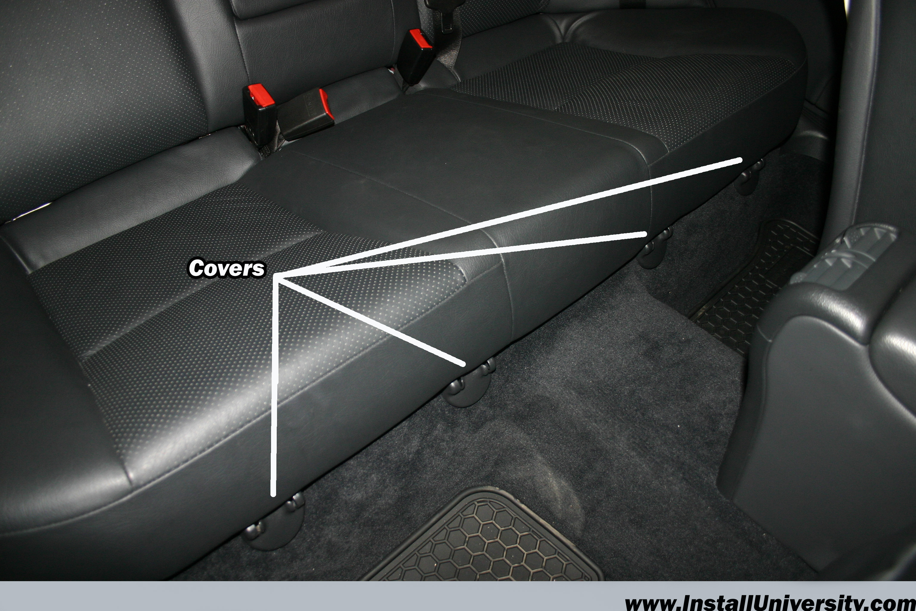
Figure 2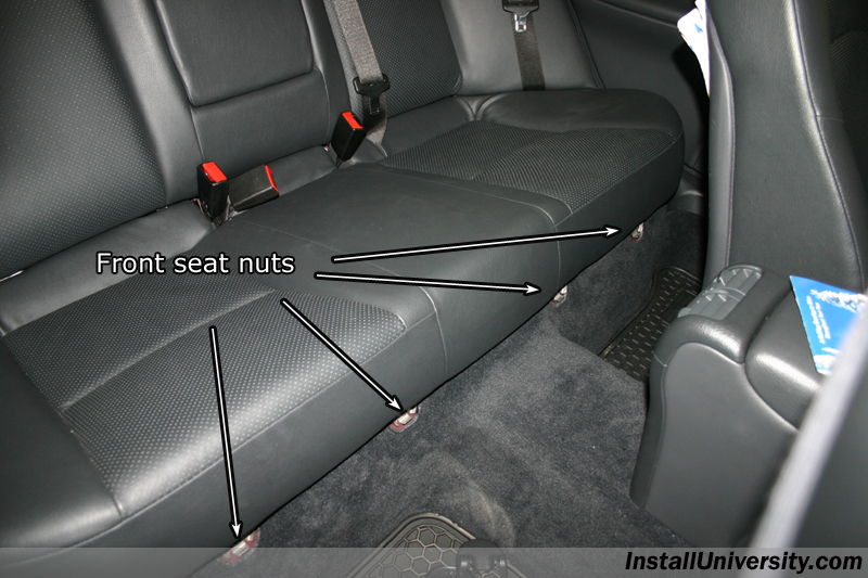
Figure 3
Figure 4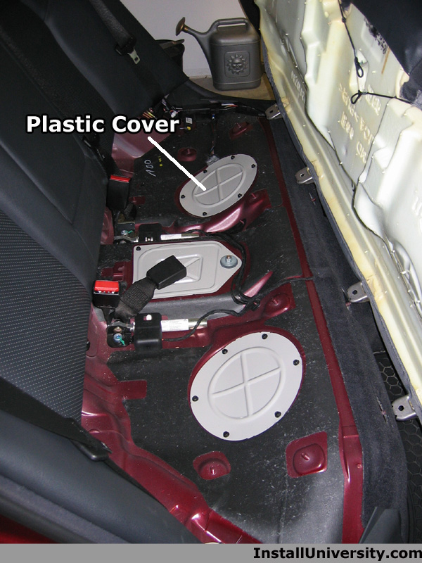
Figure 5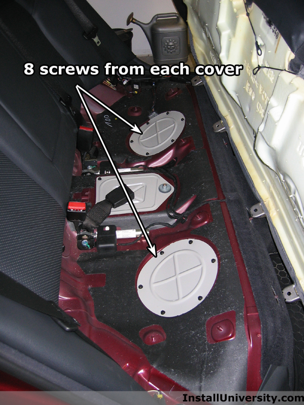
Figure 6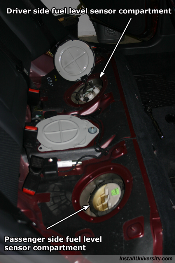
Figure 7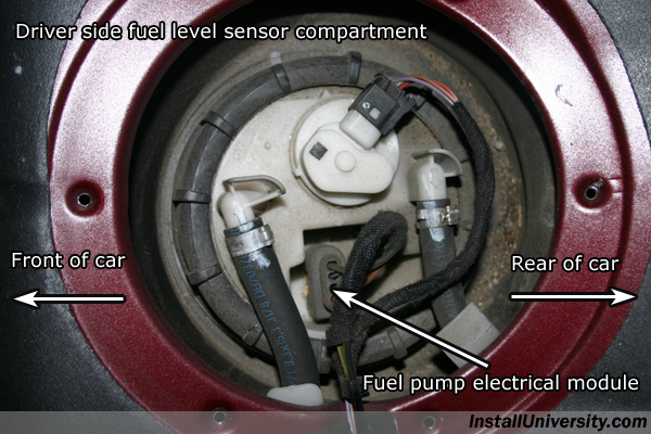
Figure 8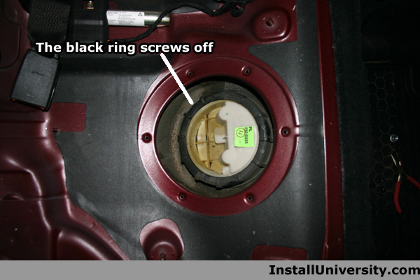
Figure 9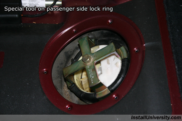
Figure 10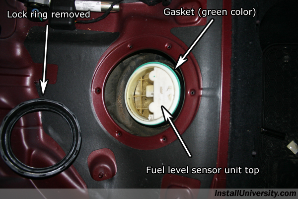
Figure 11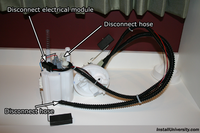
Figure 12
Figure 13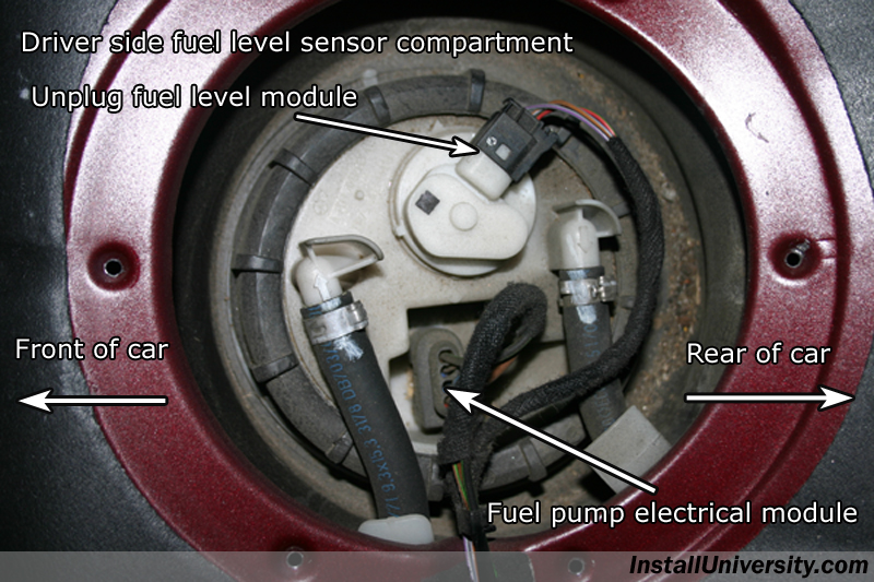
Figure 14
Figure 15
Figure 16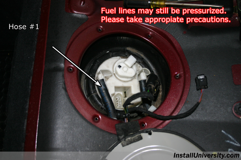
Figure 17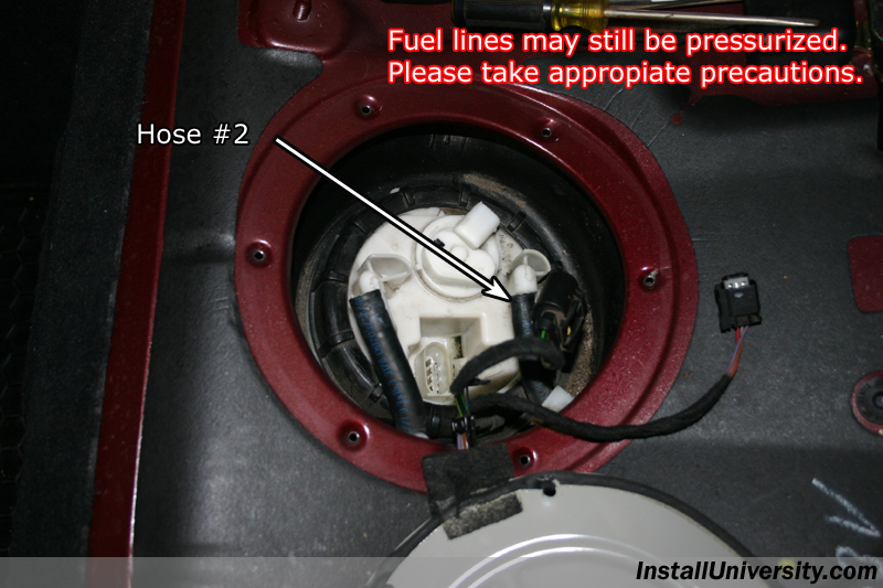
Figure 18
Figure 19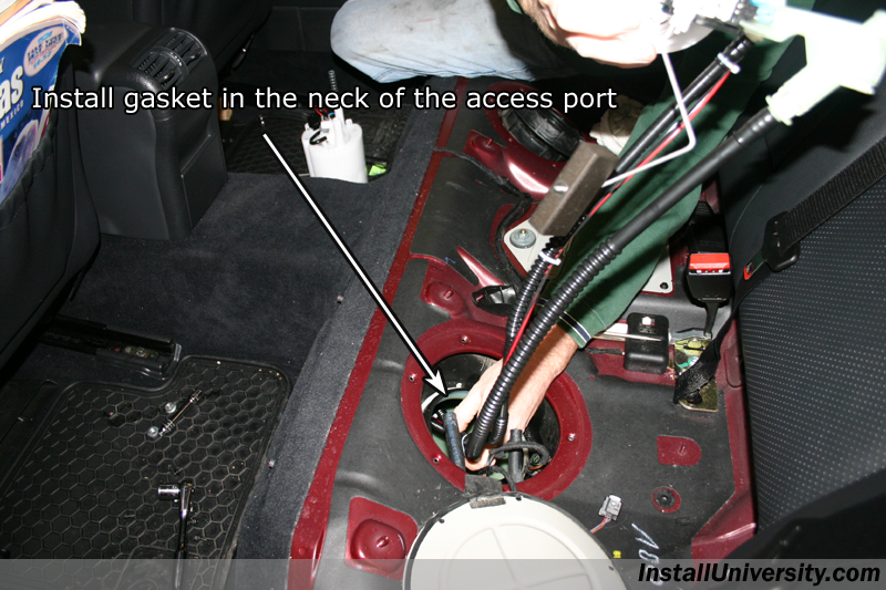
Figure 20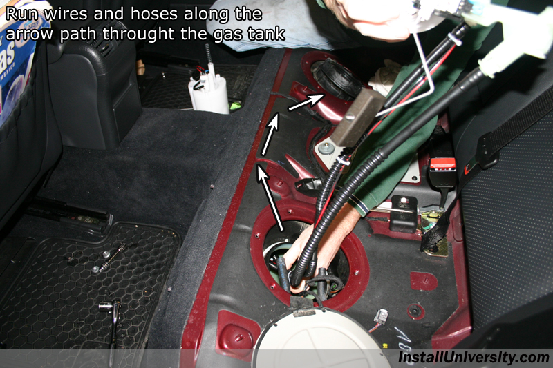
Figure 21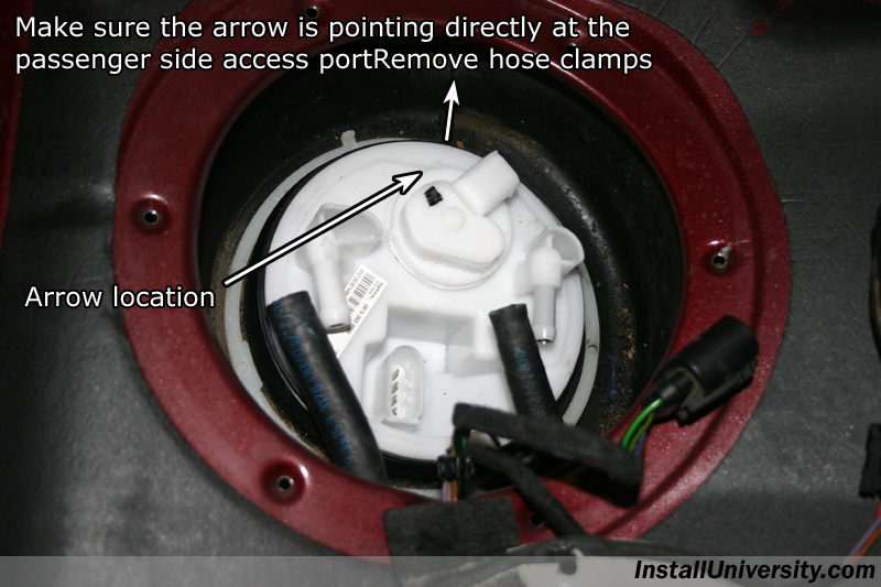
Figure 22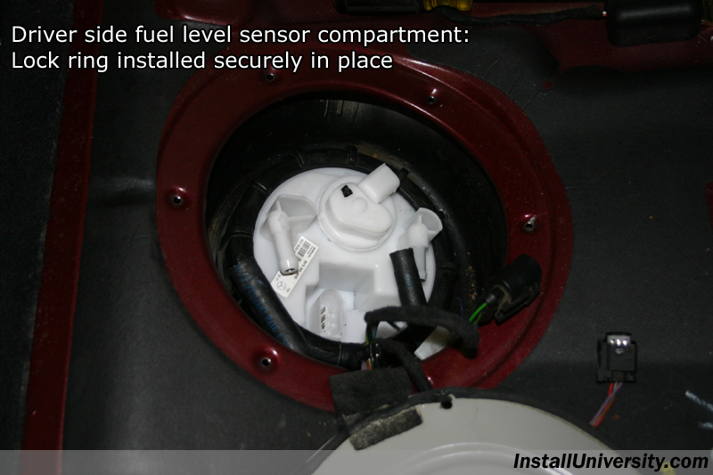
Figure 23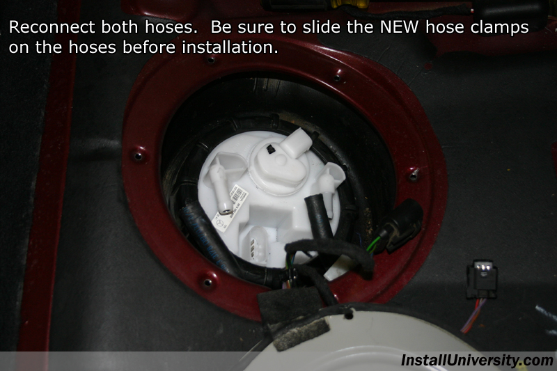
Figure 24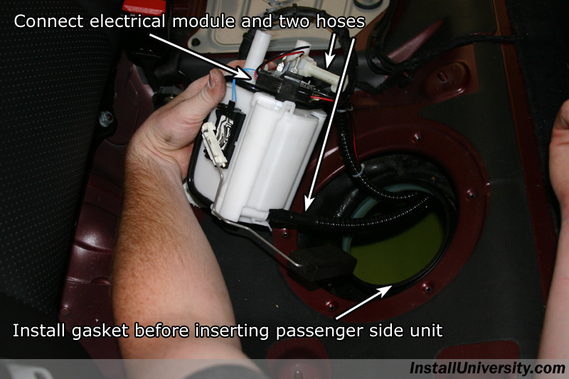
Figure 25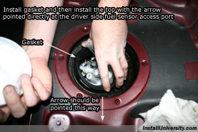
Figure 26
Figure 27
Figure 28
Figure 29
Figure 30
Figure 31
Figure 32