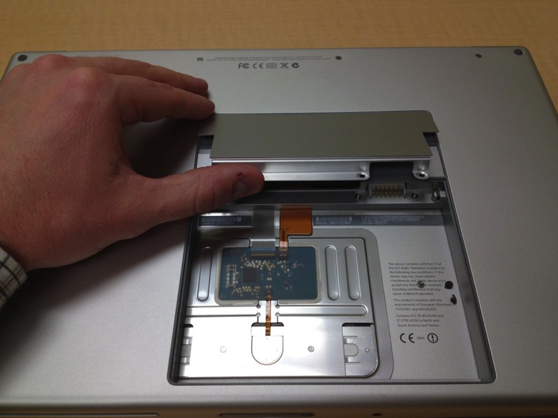
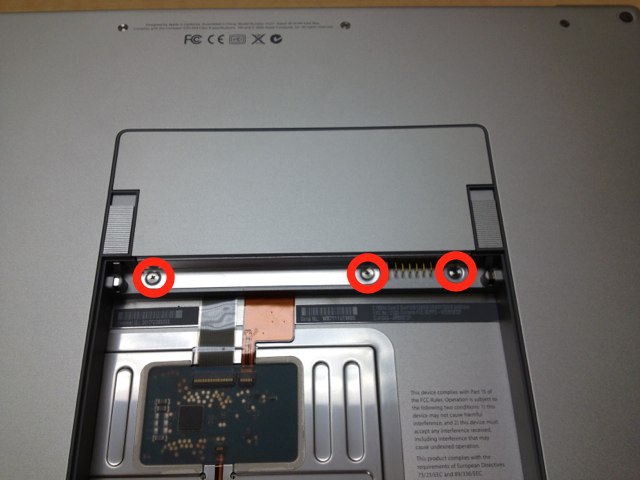
Three Phillips screws should be removed from the memory cover using a PH00 Phillips screw driver.
Remove the memory cover.
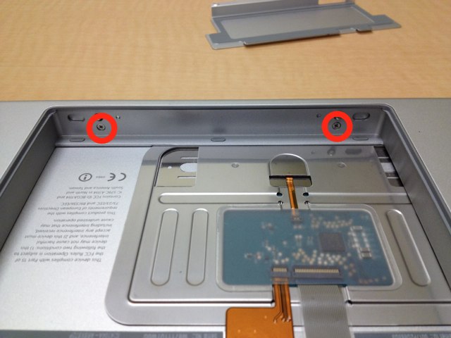
Remove the two Phillips screw inside the battery compartment closest to the outside of the case.
Remove two T6 Torx screws and four Phillips screws running along the screen hinge.
Lift the keyboard carefully. You will have to pry it up starting from the screen side working your way back to the trackpad. BE CAREFUL: There is a ribbon cable attached to the underside of the keyboard so lift carefully.
Remove the tape from the trackpad and keyboard connector. Disconnect the trackpad and ribbon cable connector from the logic board.
Disconnect the optical guide ribbon cable from the logic board. Remove tape as necessary.
Remove three Phillips screws on the side with the DVI and ethernet port.
Three Phillips screws
One T6 Torx screw
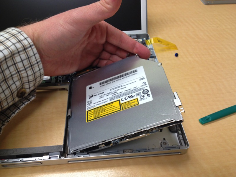
Lift the optical drive out of the case.
Remove the two Phillips screws from the side of the optical drive with the bracket. If your replacement drive already has the bracket attached, skip this step.
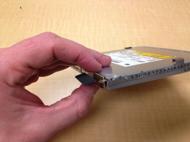
Disconnect the optical drive ribbon cable from the optical drive.
Reassemble this device by following these instructions in reverse order.