Matthew Harlan's Programmable Shift Light
Tools and
materials you will need:
Expect approximately 20 minute – 2 hour change time * If you mount your light in the same place as us you will need only about five (5) to six (6) feet of wire. Ten feet is being on the safe side. ** If you mount your light in the same place as us you will need only about one (1) to two (2) feet of wire. Note: 18 gauge wire would be the largest wire we would use and 22 gauge would be the smallest size wire we would use |
Date:
May 11, 2000 Car: 1999 Z28 Camaro, 11,900 miles Installers: Eric and Kelly Barger Email: help@installuniversity.com People who helped us from major tech talk to general advice:
Matthew Harlan's Programmable Shift light Information Page: |
When purchasing, viewing, using, and/or any
other method applied to this publication you agree to the following statements.
You, your next of kin, heirs or assigns release www.installuniversity.com,
all other persons associated in the making, production, participation, and sale
of this publication. Rephrased in plain English: When you purchase
this CD, book, or view this web page you, your next of kin, heirs or assigns
agree not to sue any associated persons with the publication for any accident or
damage in ANY form (mental or physical to your car and/or yourself) because of
this publication or your failure to heed proper safety, maintenance and/or
modification procedures. You also agree that your next of kin, heirs
or assigns cannot sue all persons associated in the making, production,
participation, and sale of this publication.
Purpose: A shift light serves several important purposes. We wanted to add the ability to know that it was time to shift without having to concentrate on the tachometer in the dash. Now we can concentrate more on the road ahead of us and shift gears when the light comes on. Also, the factory tachometer is slow in responding to the actual rpm's the car is at during a wide-open throttle first gear run. This causes us to hit the rev limiter (which is not a bad thing but not a good thing either). Now we have an accurate notification of when we need to shift! :-)
Preface: Before you remove your shift light from the plastic case please read these instructions on removal to prevent any damage to your new shift light.
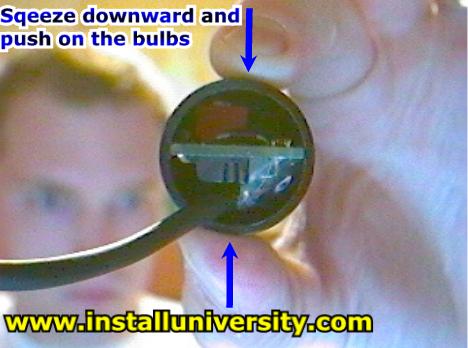
Notice: When removing the shift light squeeze the tube and push on the light bulbs. You want to squeeze the board in such a way that the sides expand out away from the sides of the board (see Figure 1 below). The board with the DIP switches and pushbuttons should slide out easily. Be careful not to pull any wires off the board.
Before you start this install be sure you know how to use all of your shop equipment. Take your time and be careful.
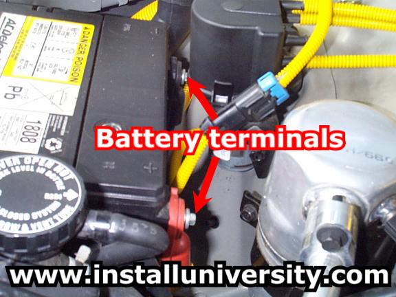
1. Disconnect the battery cables from your battery (see Figure 1). This is not some safety statement that you should skip. If you are welding on the car's frame DISCONNECT the battery cables and make sure they are touching nothing but air. You will need a 5/16 inch wrench or socket to remove the cables. If you do not perform this step you run the risk of messing up the electronics on your car including any alarm systems (factory or not).
Figure 1
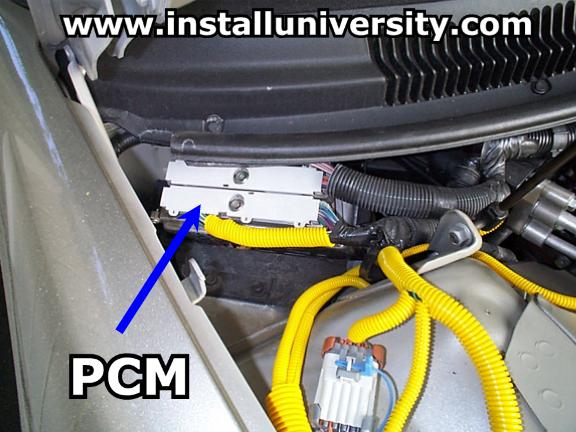
2. Raise the hood of your car and locate your PCM (see blue arrow in Figure 2).
Figure 2
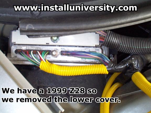
3. If you have a 1999, 2000, 2001, or 2002 model F-Body you will need to pop the gray case off of the lower part of the PCM. If you have a 1998 model you will need to pop the gray case off of the upper part of the PCM. We have a 1999 Z28 so we took the cover off the lower part of the PCM (see red arrow in Figure 3). Gently squeeze then ends of the cover and pull. They should pop out fairly easy. Then repeat this step on the opposite end. Once this is done just pull the cover completely off.
Figure 3
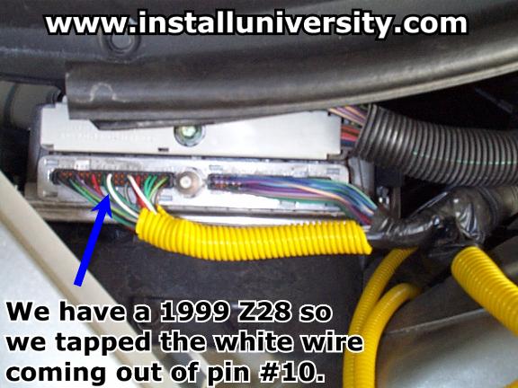
4. 1999, 2000, 2001, and 2002 model F-Body's should locate the number ten (10) pin (see blue arrow Figure 4). The wire should be white in color. 1998 model F-Body's should locate the number 35 pin (in the upper cover) and the wire should be white in color.
Figure 4
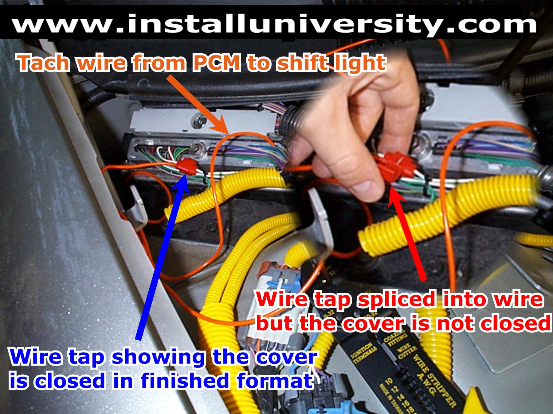
5. We used orange wire to designate the tachometer wire from the PCM to the shift light. Orange was the only color available at the time we went to the store. Color does not matter but makes it easier for future reference.
We have a 1999 Z28 so we found the number ten (10) pin and placed a wiretap assembly on the wire. You should be able to slide the wiretap assembly back and forth along the white tachometer wire. We then stuck our orange wire in the side that had the stop on the end. Your orange wire should rest up against the stop in the wiretap assembly. Then using a pair of pliers we compresses the metal slide down into the connector until it was flush across the top of the wiretap assembly. Just snap the cover on it to make sure the metal slide does not work itself loose over time (see Figure 5).
Figure 5
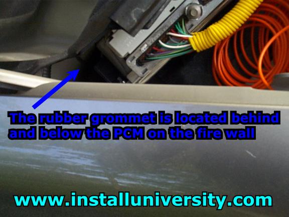
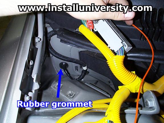
6. Now comes the most difficult part of the whole install; getting the tachometer wire through the firewall. Notice the rubber grommet behind and below the PCM (see red arrow in Figure 6).
Figure 6
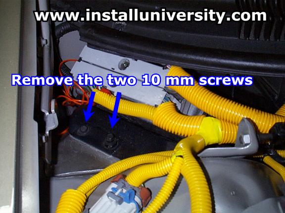
7. The easiest way to reach the rubber grommet behind and below the PCM is to remove the PCM from the car. This will give you a generous amount of room to work. Remove the two 10 mm screws on the plastic PCM holder (see Figure 7).
Figure 7
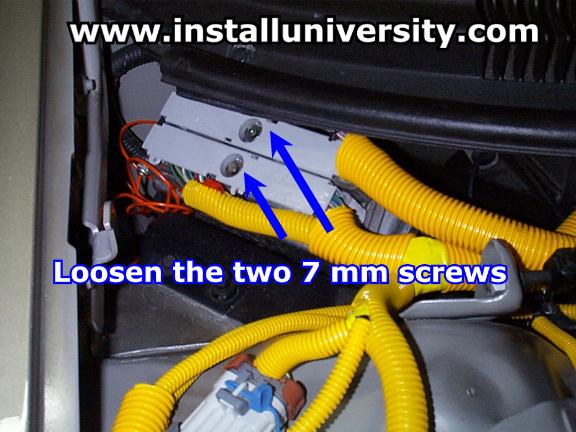
8. Loosen the two 7 mm screws on the PCM (see Figure 8). The screws will not come out of the covers.
Figure 8
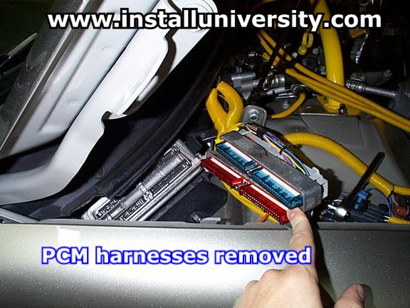
9. Gently pull the harnesses out of the PCM (see Figure 9). Once you pull the harnesses out of the PCM lay them back out of the way.
Figure 9
10. Pull the plastic PCM holder and the PCM out of the engine compartment. This took some patience and a little maneuvering but we pulled the PCM successfully out of the car in under two minutes. Locate the rubber grommet in the firewall in Figure 10.
Figure 10
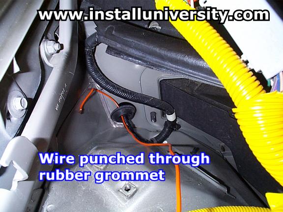
11. Pull on the rubber grommet and remove it from the wall. Take a sharp object, such as a knife, leather punch, or coat hanger, and punch a small hole through the rubber grommet. Once you have the hole punched through run your wire from the PCM to the shift light through the hole (see Figure 11 below).
Figure 11
12. Replace the rubber grommet back into the fire wall. Replace your PCM back into the engine compartment. Line up the two 10 mm screws on the plastic holder and tighten them to hand tight using your ratchet. Place the harnesses back into the PCM and tighten the two 7 mm screws, (the same screws referred to in Figure 8), to 70.8 ± 17.6 in-lb. Those torque specifications are on the top of the PCM cover; check your cover to make sure these are the correct specifications. This is a crucial step! Do NOT over tighten the screws! Use a torque wrench when performing this procedure.
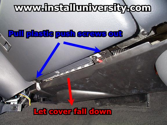
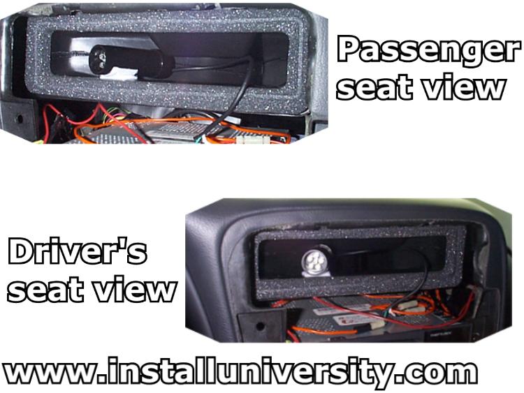
13. Before you run the wire through the hole we need to drop a cover from underneath the passenger side of the dash. You will need to pull to plastic push screws out (see blue arrows in Figure 12) and then tug on the cover and it will fall down. You don't need to pull this cover out, which would waste too much time and be unnecessary.
The wire will be coming through up and to right looking toward the firewall inside the cabin. So you can shine a flashlight up in there and see the rubber grommet. That is where you will need to pull the wire through once you have it through the wall.
Figure 12
14. We just pulled the grommet out and ran the wire through the hole and then replaced the grommet. The fit was not that good but it would work for the time being. That was the easy way out and not a good thing to do. Over time with all of the vibration the metal will rub the insulator off the wire and possibly cut it in half. We suggest you puncture a hole in the grommet instead. It appeared that we could just remove the PCM and have plenty of room. However the last thing we wanted to do was to screw our car up so we left the PCM alone since we didn't research how to remove it properly. We are going to go back and try a coat hanger (sharpened) or letter opener to puncture a hole through the grommet. Something small is preferred in this case. You will also need something to push the wire through the grommet. We are going to push a wire through the grommet on the inside and tie it to the tachometer on the outside and pull the wire back through. We will update this in the very near future.
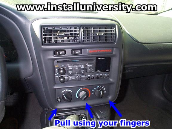
15. Now you will want to remove the trim from around the middle air-conditioning vents, radio and environment controls. It comes off in one piece and there is only one way to remove it. Just grab around the edges and pull gently (see Figure 13). Be careful after the trim comes off, the wire harnesses for ASR or TCS (traction control) and your fog lights will still be connected to the piece and the slack in the wire isn't very long.
Figure 13
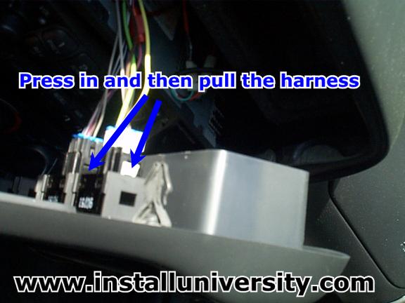
16. Now you will want to remove the wire harness connectors from ASR or TCS and your fog lights. Just take a pen or finger and press the connector in and pull (see blue arrow in Figure 14). They slide out really easy and this makes it easier for you to work with the shift light.
Figure 14
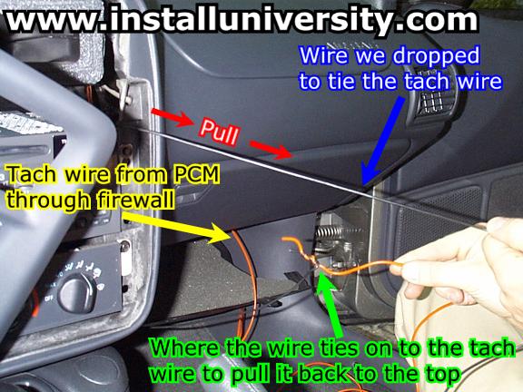
17. Now you want to get the tach wire up to the top of the radio. This can be a bit challenging if you try to push the wire up through the passenger side where the radio is. We went about this a different way and made the job very easy. We just dropped some wire down over the radio toward the passenger floorboard. When it came out of the bottom (right where the cover you dropped down in Step 13) we tied the tachometer wire to it and pulled it back up to the top (see Figure 15).
Figure 15
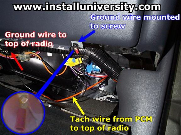
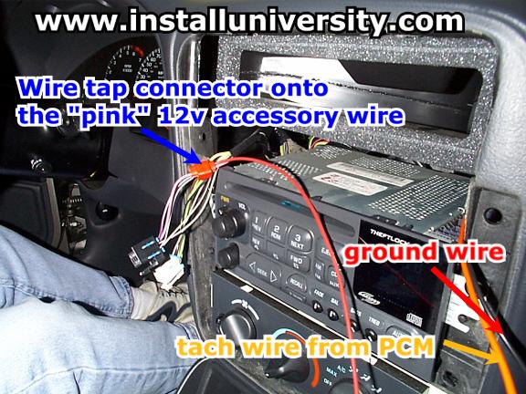
18. We ran the ground wire next. We used black wire to be our ground wire since that is the industry standard. Be sure that the ground wire is attached to something metal that is connected directly to the body of the car. We dropped the wire down over the radio toward the passenger floorboard. We ran it across the panel that you have dropped down and crimped a small connector with a loop on to the end of the wire. We unscrewed a 10 mm screw (see blue arrow in Figure 16) and placed the screw back through the fastener and retightened the screw.
Figure 16
19. You will need to find a wire that will supply 12 volts of power but only when the ignition is in the on position. Matthew Harlan made this really easy to find for us. He told me that GM makes wires that are orange have 12 volts all the time whether the car is on or not. The pink wires are 12 v accessory wires, or wires that have power just when the key is in the on position. Knowing this information made tracking down a 12v accessory wire a lot easier. We found the pink wire coming out of the ASR wiring harness (see blue arrow in Figure 17). We took a wiretap connector and tapped onto the pink wire. We used red for the color since this is usually denoted as the wire that delivers the electricity (see blue arrow in Figure 18).
Note: If you have a 1998 F-Body you need to pay close attention! You will not have a pink wire coming out of your ASR button. Teddy, (Teddy98Z28M6 on LS1.com) sent this great information to us for your information. "I got the multi meter out and found out 2 ignition wires to tap (1 solid brown and 1 striped brown/white ) on the ASR. But the only problem was the striped brown/white wire flaked out my ASR when I rev'ed the engine. It would go between off to on. The correct wire is the solid brown wire. This wire didn't cause any abnormal ABS problems." Thanks Teddy!
Figure 17
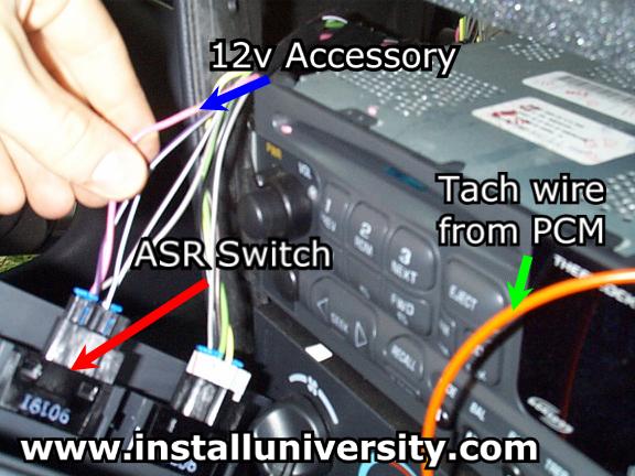
Figure 18
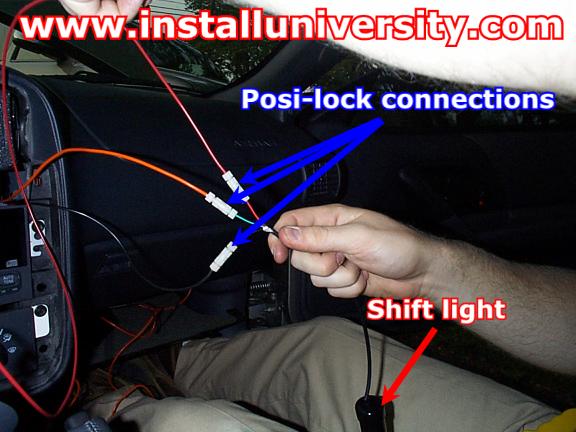
20. We are now ready to connect the ground, tachometer and our 12v accessory wires to the shift light. We used posi-lock connections to make this job quick and easy. Posi-lock connectors are way better than crimp connections and the best thing about them is you can undo them and put them back on. So if you wanted to remove your shift light, reroute a wire, you would just unscrew the connection. Then when you are ready to put the light back on or reconnect the wire you would just screw it back on when you are ready. Cool huh? They run around $2.00 at your local hardware store and you have to buy the correct size wire gauge range for you application. They were worth every penny to us.
Just remove about one half inch of the rubber insulator from around the wire and insert and screw it down. We saw these connectors on one of the hot rod shows on TNN a year or so ago. You can give the wires a good hard tug and they won't even slip a little like the couplers that you have to crimp down do. See what the posi-lock connectors look like once we get them connected in Figure 19.
Figure 19
21. Now is a good time to program and test your shift light.
Note: When removing the shift light squeeze the tube and push on the light bulbs. You want to squeeze the board in such a way that the sides expand out away from the sides of the board (see Figure 20). The board with the DIP switches and pushbuttons should slide out easily. Be careful not to pull any wires off the board.
Figure 20
This is the easiest step in our opinion. We got a little mixed up on this step and it took us a few minutes to understand what was going on. You will use the DIP switch settings twice. You will set the correct settings on the DIP switch to determine your number of cylinders and the correct setting to determine the rpm that will activate your shift light. Think of the DIP switches as a key board and the push buttons as two different memory locations. That is the easiest way for us to understand how this works. Get familiar with the DIP switches, push buttons and board in Figure 21.
Figure 21
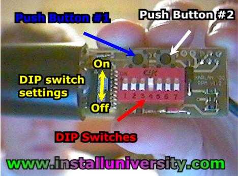
Note: When I refer to a DIP switch being "On" I mean that the DIP switch is set to the "On" position. Refer to Figure 15 to see the "On" and "Off" positions.
If
you are using your shift light in an LS1 F or Y body vehicle you will need to
set the dip switches for the number of cylinders of the car, e.g. your number of
cylinders is eight, look at the dip switch settings for eight cylinders and it
shows ON dip switch 2 (see
also Chart 1),
Off Dip switches 1, 3-7. In this case you need to turn "on" DIP
switch number two (2) and turn the rest of them down. Once you have the
correct DIP switch setting press and hold down push button number one (1) for
approximately 2 seconds (until it starts flashing repeatedly). Once the
light starts to flash repeatedly, let go of push button number one (1).
The light should flash back four (4) times to signify that you have the correct
setting.
Chart 1
| Dip Switch | 1 |
2 |
3 | 4 | 5 | 6 | 7 |
| # Cylinders | |||||||
| 6 | Off | Off | On | Off | Off | Off | Off |
| 8 | Off | On | Off | Off | Off | Off | Off |
You will then need to program the rpm you want the shift light to activate on. This is done using the "rpm" chart Harlan inserts in the install instructions (see also Chart 2). You can program the rpm setting you want in 100 rpm increments. We chose to program our shift light to 5800 rpm's. That seems to work the best with out factory 6200 rpm rev limit. I will post part of the chart from 5800 rpm's to 7000 rpm's. When you decide on the rpm to set your shift light to, you will need to reset the appropriate switches to the new position. Once you get the switches to the new position, press and hold down Push Button #2 on the board. The light should flash back the first two numbers of the rpm setting you have programmed in. In our case the light flashed five (5) times, then paused, then flashed eight (8) more times. That represents 5800 rpm's.
Chart 2
| RPM's | DIP switch | ||||||
| #1 | #2 | #3 | #4 | #5 | #6 | #7 | |
| 5600 | Off | Off | Off | On | On | On | Off |
| 5700 | On | Off | Off | On | On | On | Off |
| 5800 | Off | On | Off | On | On | On | Off |
| 5900 | On | On | Off | On | On | On | Off |
| 6000 | Off | Off | On | On | On | On | Off |
| 6100 | On | Off | On | On | On | On | Off |
| 6200 | Off | On | On | On | On | On | Off |
| 6300 | On | On | On | On | On | On | Off |
| 6400 | Off | Off | Off | Off | Off | Off | On |
| 6500 | On | Off | Off | Off | Off | Off | On |
| 6600 | Off | On | Off | Off | Off | Off | On |
| 6700 | On | On | Off | Off | Off | Off | On |
| 6800 | Off | Off | On | Off | Off | Off | On |
| 6900 | On | Off | On | Off | Off | Off | On |
| 7000 | Off | On | Off | Off | Off | Off | On |
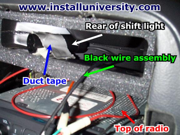
22. We then mounted the shift light in the air conditioning vent directly over the radio behind the left vent. We used velcro that we purchased at the local Wally World. It only took one little square less that measured 1/2 x 1/2 inches (see Figure 22 below).
We placed a little bit of the pigtail from the shift light into the air conditioning vent and let the black wire assembly that exits out of the rear of the shift light hang over the foam material used to seal the vents from the inside. We shoved the rest of the wire slack onto the top of the radio.
Figure 22
23. Then just hook up the ASR and fog light harnesses back up, replace the front trim piece, put the cover under the glove box back and there you have it. You are done.
Here is a picture of the shift light "flashing" from inside the air conditioning vent.
Figure 23
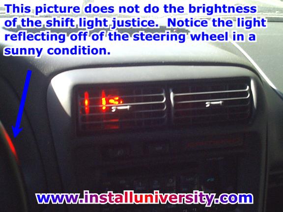
Comments: We tested the light on the interstate (they had a drunk driver pulled over near our house and I didn’t want to get 5 cops after me). We tested the light with the ASR button on and off. It worked flawlessly both times! We love the light and you cannot miss it during the day or at night (especially at night). We chose red for one reason. It is the only color that will not hinder night vision when flashed in your eyes.
We came back to this install and removed the duct tape from the A/C vent and replaced it with velcro (see Figure 24). We highly recommend you do the same because the duct tape blocks a lot of the air from exiting out of the vent. We used duct tape to hold the shift light down because this was the most convenient item we had to make a mount with (and it was free).
Figure 24
Web Author: Eric Barger help@installuniversity.com
Copyright © 1999 - 2002 Eric Barger. All rights reserved.
Revised: June 07, 2007.