| August 30, 2000 |
Going with the Flow
Decisions, decisions...
Before any parts are flowed on a flow bench you have to decide what parameters are going to be used for the test. There is more to it than just showing up and having your parts flowed. You should sit down and make a few calculations and decide what you are looking for before having the test performed. Taking a little time in the beginning will make the job less stressful in the end.
Calculating assumed air flow
Knowing the air flow in cubic-feet per minute (cfm) your car can take in at the given engine speed (rpm) is an absolute must for understanding your induction system. You need to decide a few things before diving headfirst into this ocean of the unknown. What is the displacement of your engine? For what maximum rpm do you want to design? Do you have a four- or two-stroke engine? What is the volumetric efficiency (V.E.) of your engine?
Since we own a 1999 Camaro Z28, we will use the LS1 with no internal engine modifications as our design engine. Our LS1 has a displacement rating of 346 cubic inches (in3). We do not want to push our engine past the 6,200 rpm rev-limiter. So, we will use 6,000 rpm as our maximum rpm for the design. Our engine is a four stroke engine like all pushrod V-8's on the road. Having a four-stroke engine is represented by a value of two. We have to assume a volumetric efficiency for this engine because a stock LS1 will not operate at 100% efficiency. We will assume 80% volumetric efficiency for the purpose of these calculations. The required air flow a stock LS1 will pump at 80% volumetric efficiency is 480.56 ft3/minute (see Equation 1). Equation 1 is for electronic fuel injected cars.
Equation 1 2
![]()
Where:
rpm
= maximum design rpm
RAF
= Required air flow (ft3/minute)
VE
= Volumetric efficiency
ED
= Engine displacement (in3)
ES
= Engine stroke (2 for a four stroke engine)
C
= Conversion factor from in3 to ft3
Solving for Required Air Flow:
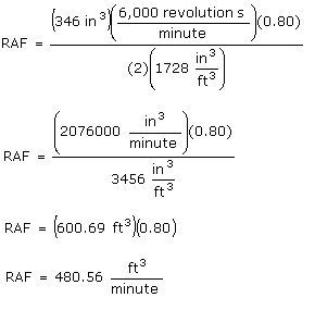
480.56 ft3/minute is the same amount of air that will have to flow through the induction system into the engine. This air needs to flow as easily as possible into the engine. The only way for us to know how easily the air is flowing from the time it enters the mass-air-flow housing to the time it exits the throttle body is to have the following parts tested on a flow bench: mass-air-flow housing and sensor, rubber bellow, and throttle body.
Determining test conditions
We learned from our previous article that the pressure drop that a part is flowed at represents how hard the engine has to work for air to flow through the parts. Unless you are able to perform a flow test on the engine while in operation, you have to decide at what pressure drop you want to flow your parts. Since most people do not have the money or means to perform a pressure test on the induction system while in operation, the tests are performed on the individual parts on a flow bench. This is much cheaper and convenient considering almost all performance shops have their own flow bench.
How does a person decide at what pressure drop or flow rate they want the parts flowed? Knowing that you can convert your data to another pressure drop or flow rate eases the pain in deciding. For most tests, it is best to pick a pressure drop around the middle of the maximum and minimum measurements on the flow bench. Most flow benches can perform a maximum pressure drop of 28 inches of H2O. Having the test performed at a 14 inches of H2O pressure drop would help minimize any conversion errors to another pressure drop or flow rate at the extremes of the conversions. Equation 2 can be used to calculate the flow rate for a desired pressure drop. You can also rearrange the equation so that you can find the desired pressure drop for a given flow rate.
Equation 2 3

Where:
FR0
= Flow rate at original pressure drop (ft3/minute)
FR1
= Flow rate (ft3/minute)
PD0
= Original pressure drop (inches of H2O)
PD1
= Desired pressure drop (inches of H2O)
Flowing a part at a 28 inches of H2O pressure drop will report back high flow rates. Those flow rates are useless bits of information for most conditions. For example, let's pretend we have a throttle body for a LS1 that flows 600 cfm at 28 inches of H2O. The gut reaction is to say that the throttle body flows enough air for the engine and is not a restriction. When you back solve, using Equation 2, you find out the pressure drop for 481 cfm for the same throttle body is a 17.99 inches of H2O pressure drop.
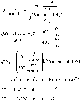
The calculation shows us that the throttle body will provide the 481 cfm needed by a stock LS1; however, the pressure drop shows us the engine has to supply a great deal of work (suction) to get that 481 cfm. The lower that pressure drop the better; 18 inches of H2O pressure drop to supply your 481 cfm is not ideal either. You would hope that the pressure drop to produce the needed 481 cfm would be under 10 inches of H2O. So take the advice from the previous section unless you need data for special circumstances. You want to have your test performed closer to your parts everyday operating conditions.
| Author: Eric
Barger Editors: Tom Deskins & Kelly Barger |
- Eric Barger
![]()
Works Cited
1. Deskins, Tom. Interview.
2. Vizard, David. How to Build Horsepower. Volume 2. Page 60.
3. Vizard, David. How to Build Horsepower. Volume 2. Page 63.
Web Author: Eric Barger help@installuniversity.com
Copyright © 1999 - 2002 Eric Barger. All rights reserved.
Revised: June 07, 2007.